Connecting Networks to OpenVPN Cloud Using Connectors | OpenVPN
To make the routing work the following needs to be done:
- Connector software needs to be installed on a computer in HQ Network (see, the section on Connector installation)
- Routing needs to be enabled on the computer running the Connector software (see, the section on enabling routing)
- Either NAT must be enabled on the computer running the Connector software (see, the section on enabling NAT) OR a static route needs to be added to the router on HQ Network (see, section on static routing)
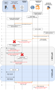
- The admin adds a Network using the OpenVPN Cloud Administration portal. The name of ‘HQ Network’ is given to the Network and 10.0.0.0/18 is added as its subnet.
- OpenVPN Cloud in the background assigns 100.96.0.100 as the VPN IP address for the Connector created for HQ Network and configures its routing table to route all traffic destined to the HQ Network’s subnets (10.0.0.0/18) to be forwarded to its Connector (100.96.0.100).
- Admin downloads and installs the connector software and connects with the OpenVPN Cloud profile to establish VPN connection to the preconfigured OpenVPN Cloud VPN Region.
- During VPN connection establishment OpenVPN Cloud pushes down a route to the VPN Subnet range (100.96.0.0/11)
- Once the connection is established, the VPN is represented by a virtual interface that receives packets from the VPN and will be used to send packets destined to 100.96.0.0/11.
- Admin configures a User named Bob in a User Group that has its Internet Access set to (Split-tunnel ON).
- Bob receives the invitation email, downloads the Connect client, and imports the profile after selecting the closest VPN Region.
- On connection, because split-tunnel is ON the virtual interface receives routes for both the OpenVPN Cloud VPN IP subnet range as well as the subnet range of HQ Network.
- Bob tries to access the HR application. As the HR application is in the HQ Network the packet is routed via the VPN interface.
- When OpenVPN Cloud receives the packet it checks its routing table and directs the packet to the Connector in HQ Network because of the destination IP address being in subnet configured for HQ Network.
- When the Connector instance receives the packet destined to 10.0.0.20 it drops it because the computer only expects to receive packets destined to it at either 10.0.0.10 or 100.96.0.100.
- In order for the Connector instance to accept the packet destined at 10.0.0.20 received from its VPN interface and send it to the HQ Network LAN, the Connector needs to be configured to act as a router and forward IP packets using the right interface. Please see the section on “Enable Routing”
- Now that routing is enabled, the Connector instance forwards the received packet on the LAN interface in order to reach the HR Application server.
- The Application server responds to the packet and because of not knowing where to send the packet destined to an IP address in 100.96.0.0/11 it sends it to its default route which is the router.
- When the router receives the packet, it drops it because there are no entries on how to route this packet, and the destination IP address is not routable on the internet.
- To resolve this issue, a static route can be added to the router informing it to forward all traffic destined to 100.96.0.0/11 to the Connector instance. See section for “Add Static Routes” for references.
- With the static route in place, the packet is forwarded to the Connector instance which, being already configured as a router, can route it via the VPN to its final destination (steps 21-22)
- As an alternative to configuring the router with a static route, NAT can be enabled on the Connector instance. When NAT is turned ON, the Connector instance will substitute its IP address for the original source IP address, and on receiving the response, switch the destination to the original source IP. Please see the section on ‘Enable NAT’
- The packet now gets forwarded by the Connector instance as well as undergoes NAT so that when the packet is received by the Application Server it need not forward the response to the router but send the response right back to the Connector Instance
- On receiving the response, the Connector instance translates the destination and can forward the response on the VPN interface
- The response reaches the Connector instance either by use of Option 1 (static route) or Option 2 (NAT) and is sent to OpenVPN Cloud
- OpenVPN Cloud forwards the packet to Bob.
HQ Network being used as VPN egress route
In this traffic flow, we see how internet traffic exiting OpenVPN Cloud and egressing from HQ Network is handled.
As shown in the figure, HQ Network is made up of the 10.0.0.0/18 subnet and a computer running Ubuntu is acting as the Connector on IP address 10.0.0.10. The HQ Network is connected to the Internet by a router that performs Network Address Translation (NAT) to provide the computers on the internal private network with access to the Internet. The service on the internet that is being accessed by Bob is at the IP address of 107.3.152.27.
To make the routing work the following needs to be done:
- Connector software needs to be installed on a computer in HQ Network (see, the section on Connector installation)
- Routing needs to be enabled on the computer running the Connector software (see, the section on enabling routing)
- Either NAT must be enabled on the computer running the Connector software (see, the section on enabling NAT) OR a static route needs to be added to the router on HQ Network (see, section on static routing)
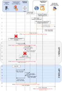
- The admin marks HQ Network as an egress route for the VPN using the OpenVPN Cloud administration portal.
- In the background, OpenVPN Cloud adds the IP address of the HQ Network Connector as the default route for the VPN.
- The admin sets the internet access of the User Group to which Bob belongs to Split Tunnel OFF
- Bob’s VPN connection is reset and OpenVPN Cloud is made the default route destination.
- Bob tries to access an Internet application (server IP address of 107.3.152.27). As OpenVPN Cloud is the default route, the packet is routed via the VPN interface.
- When OpenVPN Cloud receives the packet it checks its routing table and directs the packet to the Connector in HQ Network because it has been set as the egress route for the VPN.
- When the Connector instance receives the packet destined to 107.3.152.27 it drops it because the computer only expects to receive packets destined to it at either 10.0.0.10 or 100.96.0.100.
- In order for the Connector instance to accept the packet destined at 107.3.152.27 received from its VPN interface and send it to the HQ Network LAN, the Connector needs to be configured to act as a router and forward IP packets using the right interface. Please see the section on “Enable Routing”
- Now that routing is enabled, the Connector instance forwards the received packet on the LAN interface in order to reach the Network’s router.
- The router performs NAT and forwards the packet to the server on the Internet.
- When the router receives the response, it performs the NAT translation to get the destination address as an IP address in 100.96.0.0/11
- The router drops the response because there are no entries on how to route this packet, and the destination IP address is not routable on the internet.
- To resolve this issue, a static route can be added to the router informing it to forward all traffic destined to 100.96.0.0/11 to the Connector instance. See section for “Add Static Routes” for references.
- With the static route in place, the packet is forwarded to the Connector instance which, being already configured as a router, can route it via the VPN to its final destination (steps 20-21)
- As an alternative to configuring the router with a static route, NAT can be enabled on the Connector instance. When NAT is turned ON, the Connector instance will substitute its IP address for the original source IP address, and on receiving the response, switch the destination to the original source IP. Please see the section on ‘Enable NAT’
- The packet now gets forwarded by the Connector instance as well as undergoes NAT so that when the packet is received by the router the source IP address is 10.0.0.10 and not the IP address in 100.96.0.0/11
- The router performs NAT and forwards the packet to the server on the Internet.
- When the router receives the response, it performs the NAT translation to get the destination address as 10.0.0.10 (because the Connector instance had performed NAT on step 16) and forwards the response to the Connector instance.
- On receiving the response, the Connector instance translates the destination back to the IP address in 100.96.0.0/11 and can forward the response on the VPN interface
- The response reaches the Connector instance either by use of Option 1 (static route) or Option 2 (NAT) and is sent to OpenVPN Cloud
- OpenVPN Cloud forwards the packet to Bob.
Site-to-Site
The flow below shows the traffic flows between two sites connected to OpenVPN Cloud: HQ Network and Branch Network.
To make the routing work the following needs to be done:
- Connector software needs to be installed on a computer in HQ Network and Branch Network (see, the section on Connector installation)
- Routing needs to be enabled on the computer running the Connector software (see, the section on enabling routing)
- For proper routing here it is mandatory to add static routes to the network routers on both sites. As new sites are added to OpenVPN Cloud, it is mandatory to add to the existing static routes on each site with a route to the new network’s subnets. See, the section on static routing.
- Additionally, NAT can be enabled on the Connector instance too if there are internal firewalls or security groups around your application servers that accept packets only from subnets belonging to the local network (see, the section on enabling NAT).
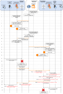
- The Administrator adds a Network using the OpenVPN Cloud Administration portal. The name of ‘HQ Network’ is given to the Network and 10.0.0.0/18 is added as its subnet.
- OpenVPN Cloud in the background assigns 100.96.0.100 as the VPN IP address for the Connector created for HQ Network and configures its routing table to route all traffic destined to the HQ Network’s subnets (10.0.0.0/18) to be forwarded to its Connector (100.96.0.100).
- Admin downloads and installs the connector software and connects with the OpenVPN Cloud profile to establish VPN connection to the preconfigured OpenVPN Cloud VPN Region.
- During VPN connection establishment OpenVPN Cloud pushes down a route to the VPN Subnet range (100.96.0.0/11)
- Once the connection is established, the VPN is represented by a virtual interface that receives packets from the VPN and will be used to send packets destined to 100.96.0.0/11.
- In order for the Connector instance to accept the packets received from its VPN interface and send it to the HQ Network LAN, the Connector needs to be configured to act as a router and forward IP packets using the right interface. Please see the section on “Enable Routing”
- A static route is added to the router informing it to forward all traffic destined to OpenVPN Cloud (100.96.0.0/11) to the Connector instance. See section for “Add Static Routes” for references.
- The Administrator adds a Network using the OpenVPN Cloud Administration portal. The name of ‘Branch Network’ is given to the Network and 192.168.0.0/22 is added as its subnet.
- OpenVPN Cloud in the background assigns 100.96.0.300 as the VPN IP address for the Connector created for Branch Network and configures its routing table to route all traffic destined to the Branch Network’s subnets (192.168.0.0/22) to be forwarded to its Connector (100.96.0.300).
- VPN Connection to HQ Network’s Connector is quickly reset to push the new route of 192.168.0.0/22
- Now the VPN virtual interface will be used to reach both OpenVPN Cloud and Branch Network.
- Admin downloads and installs the connector software and connects with the OpenVPN Cloud profile to establish VPN connection to the preconfigured OpenVPN Cloud VPN Region.
- During VPN connection establishment OpenVPN Cloud pushes down a route to the VPN Subnet range (100.96.0.0/11) and the HQ Network subnet range 10.0.0.0/18.
- Once the connection is established, the VPN is represented by a virtual interface that receives packets from the VPN and will be used to send packets destined to 100.96.0.0/11 and 10.0.0.0/18.
- In order for the Connector instance to accept the packets received from its VPN interface and send it to the HQ Network LAN, the Connector needs to be configured to act as a router and forward IP packets using the right interface. Please see the section on “Enable Routing”
- A static route is added to the router informing it to forward all traffic destined to OpenVPN Cloud (100.96.0.0/11) to the Connector instance. See section for “Add Static Routes” for references.
- A computer on HQ Network now tries to reach the Finance Server on the Branch Network. It sends the packet to the network’s router.
- The router drops the packet because it has no route to reach the 192.168.0.0/22 network.
- A static route is added with the Connector instance as the destination for the Branch Network subnet
- Now, the packet is forward to the Connector instance from the router
- With routing already enabled, the Connector instance sends the packet to OpenVPN Cloud using the VPN interface
- OpenVPN Cloud forwards the packet on to the Connector instance in Branch Network
- When the Connector instance receives the packet destined to the Finance Server it forwards it on the LAN interface because it had been already setup as a router.
- The Finance Server responds to the request but send it to the network’s router because the destination IP address of 10.0.0.0.13 does not belong to its LAN
- The router forwards the packet to the Connector because of the static route configured for 100.96.0.0/11
- With routing already enabled, the Connector instance sends the packet to OpenVPN Cloud using the VPN interface
- OpenVPN Cloud forwards the packet on to the Connector instance in HQ Network
- When the Connector instance receives the packet destined to the computer on its LAN it forwards it on the LAN interface because it had been already setup as a router.
- Now, a computer on the Branch network tries to access the HR server that is in the HQ network by sending the request packet to the router.
- As the router does not have a static route for the HQ network IP address range, it needs to be added in order to send the traffic flow to the Connector
Installation of Connector
The steps for installation of the Connector are the same regardless of its use a Host or a Network connector.
Enable Routing
Routing on Linux
To enable IPv4 forwarding, use the following commands on the command line:
sed -i 's/#net.ipv4.ip_forward=1/net.ipv4.ip_forward=1/g' /etc/sysctl.conf
sysctl -p
This will enable forwarding in the Linux kernel.
Routing on Windows
Please look at the documentation for your specific Windows version. For your convenience references on how to deploy the Routing and Remote Access Service for Windows Server 2016 are given below.
After installation of the routing and remote access service, do the following:
- From Server Manager, click Tools, and select Routing and Remote Access
- From the Routing and Remote Access window, right-click the server, and select Configure and Enable Routing and Remote Access.
- On the first page of the setup wizard, click on the Next button
- Select Custom configuration and click on the Next button
- Select LAN routing and click on the Next button
- On the summary page, click on the Finish button
- Finally, to start the service, click on the Start service button and wait for the service to start. The dot on the server will turn the color green from the color red
- Now, expand the server and expand IPv4 entry to click on the General node. The computer is now acting as a router between the interfaces shown.
See, Connecting to a Windows Server 2016 Network
Routing on macOS
Open the Terminal application and type
sysctl -w net.inet.ip.forwarding=1Enable NAT
NAT on Linux
Use the following commands on the command line:
apt install iptables-persistent
iptables -t nat -A POSTROUTING -o eth0 -j MASQUERADE
iptables-save > /etc/iptables/rules.v4
The rule uses the NAT packet matching table (-t nat) and specifies the built-in POSTROUTING chain for NAT (-A POSTROUTING) on the external networking device (-o eth0). POSTROUTING allows packets to be altered as they are leaving the Connector instance. The -j MASQUERADE target is specified to mask the private IP address of a node with the IP address assigned to eth0.
The above is sufficient if you are fine with all traffic being NATted. However if you need hosts on the network to distinguish between different VPN clients or connectors, you need to use “! -d xx.xx.xx.xx/xx” in the NAT rule where xx.xx.xx.xx/xx is the subnet of the target LAN subnet, otherwise traffic to that subnet will also be NATted.
iptables -t nat -A POSTROUTING -o eth0 ! -d 10.10.0.0/16 -j MASQUERADENAT on Windows
A tutorial can be found here https://www.youtube.com/watch?v=a1xYi6pxA_4
NAT on macOS
Use OS X’s built-in Internet Sharing
Special Considerations for IaaS
SECURITY GROUPS
If you are using Security Groups to protect any instances that need their traffic to be routed through the Connector instance, you need to add the Security Group of the Connector instance to their inbound rules.
AWS:
https://docs.aws.amazon.com/vpc/latest/userguide/VPC_SecurityGroups.html
Set Source/Dest Check
Virtual servers provided by IaaS providers use virtual network interface cards (VNIC). By default, every VNIC performs the source/destination check on its network traffic. The VNIC looks at the source and destination listed in the header of each network packet. If the VNIC is not the source or destination, then the packet is dropped.
In order for the instance on which the Connector is installed to perform routing or NAT functionality the Source/Dest check on the VNIC needs to be turned OFF.
Please refer to the documentation provided by your IaaS provide to disable source/dest check. For your convenience documentation references are provided below:
AWS: https://docs.aws.amazon.com/vpc/latest/userguide/VPC_NAT_Instance.html#EIP_Disable_SrcDestCheck
Oracle: https://docs.cloud.oracle.com/en-us/iaas/Content/Network/Tasks/managingVNICs.htm#Source/D
Azure: IP forwarding must be enabled at the VNIC https://docs.microsoft.com/en-us/azure/virtual-network/virtual-network-network-interface#enable-or-disable-ip-forwarding
GCP: https://cloud.google.com/vpc/docs/using-routes#canipforward
Also, note that when running some Linux firewall packages, rpfilter is sometimes turned on
https://tldp.org/HOWTO/Adv-Routing-HOWTO/lartc.kernel.rpf.html. In addition to source/dest check, rp_filter in sysctl.conf should be turned off.
AWS Route Updates
If you have followed the instructions for using CloudFormation to install Connector on AWS, any needed static routes will be added to the VPC route table by the Connector. There is no need to manually add static routes in the VPC route table.
Add Static Routes
All routers provide an ability to add a static route. Please refer to your router documentation. For Virtual Cloud Networks, we have provided references below for some IaaS providers.
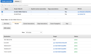
A static route needs to be added to the VPN IP address range of OpenVPN Cloud. The default VPN IP address range is 100.96.0.0/11 for OpenVPN Cloud. The static route added should have 100.96.0.0/11 as the destination IP address range and the private IP address of the Connector instance as the Target.
A static route needs to be added for the destination subnet ranges of your other Networks that are connected to OpenVPN Cloud too.
The figure below shows the static routes added to a VPC route table. You can see that there are three routes pointing to eni-06e725657ba3a8f63 (the instance that is running the connector software). 172.31.0.0/16 is the subnet of another Network that can be accessed via OpenVPN Cloud.
AWS: If you have followed the instructions for using CloudFormation to install Connector on AWS, any needed static routes will be added to the VPC route table by the Connector. There is no need to manually add static routes in the VPC route table. See, Launch Connector on AWS
Azure: Azure calls static routes as ‘user-defined’. See, https://docs.microsoft.com/en-us/azure/virtual-network/virtual-networks-udr-overview
GCP: https://cloud.google.com/vpc/docs/using-routes
Oracle Cloud: See, using Private IP as a route target https://docs.cloud.oracle.com/en-us/iaas/Content/Network/Tasks/managingroutetables.htm#Route